Downloaded 2,156 times


The document discusses a project that measures heart rate using an infrared pulse sensor and Arduino technology, addressing the need for accessible heart monitoring due to a large population at risk of heart attacks. It outlines the hardware components, software, and design of the sensor, which detects blood flow by reflecting infrared light. Future applications for this monitoring system could include tracking additional health parameters and facilitating telemedicine for remote patient monitoring.
Presented by Varsha Khandagale, Sampada Kulkarni, Himali Patil.
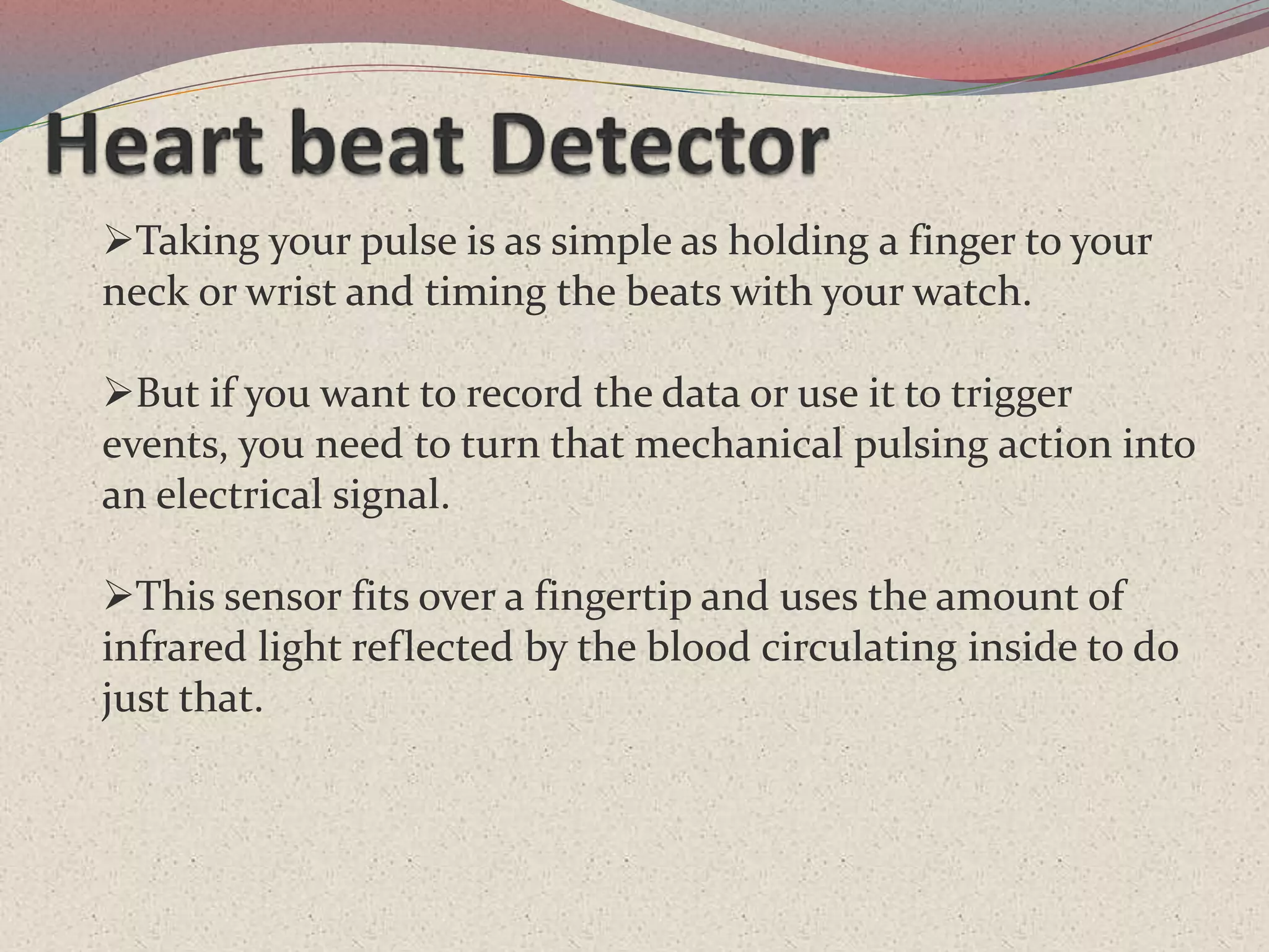
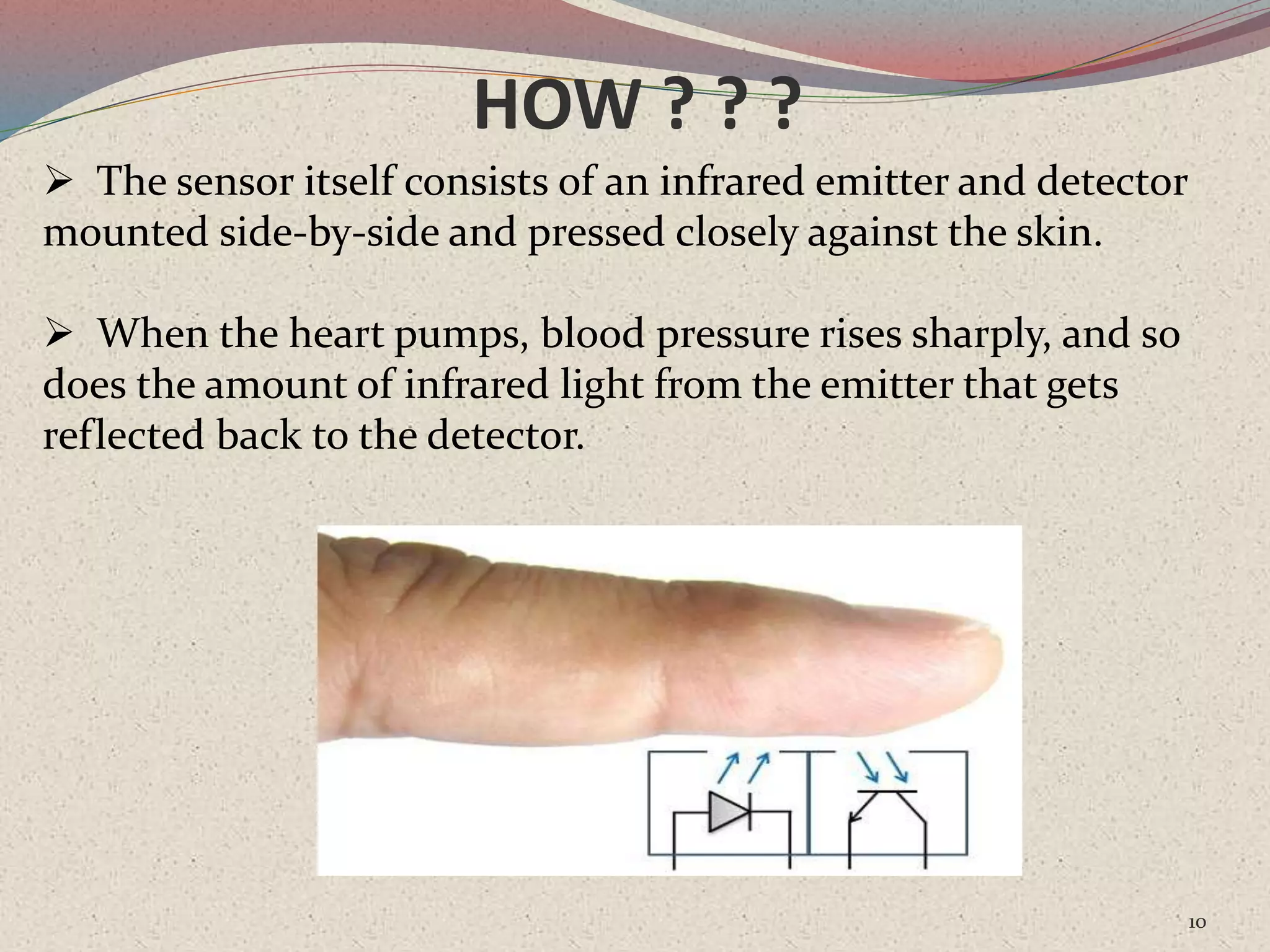
Pulse measurement uses a fingertip sensor to convert mechanical actions into electrical signals using infrared light.
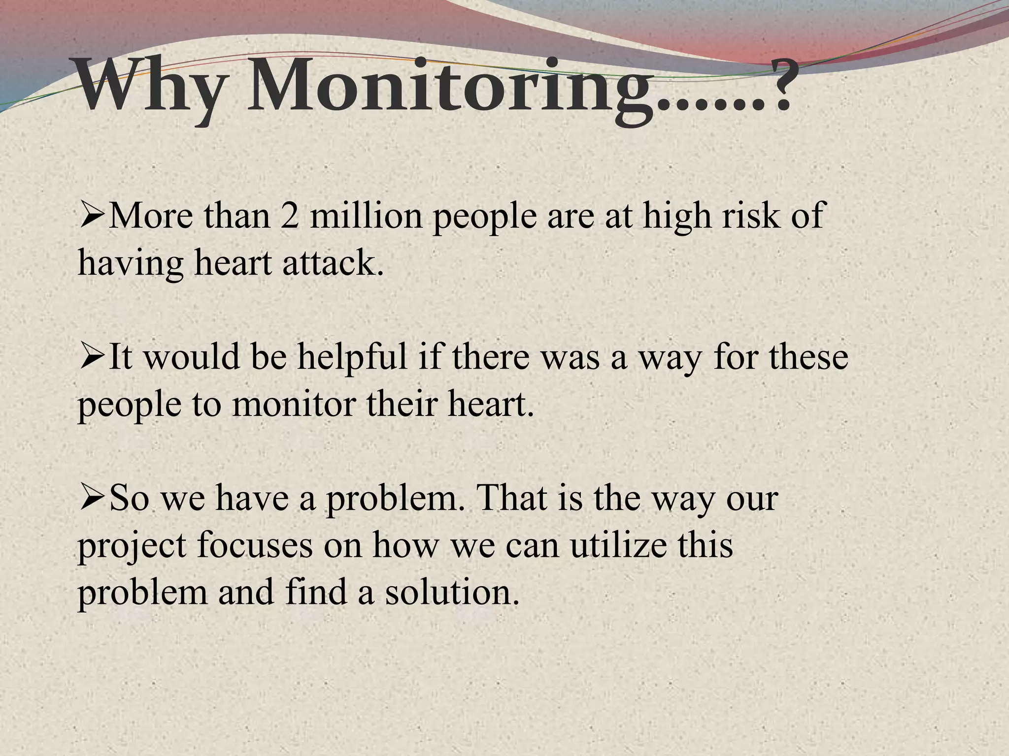
Over 2 million people are at high risk of heart attacks, highlighting the necessity for effective heart monitoring solutions.
Current methods like stethoscopes are inaccurate, while electrocardiograms are costly and user-unfriendly.
This project utilizes an IR pulse sensor with Arduino to measure heartbeats for 10 seconds, displaying results on a screen.
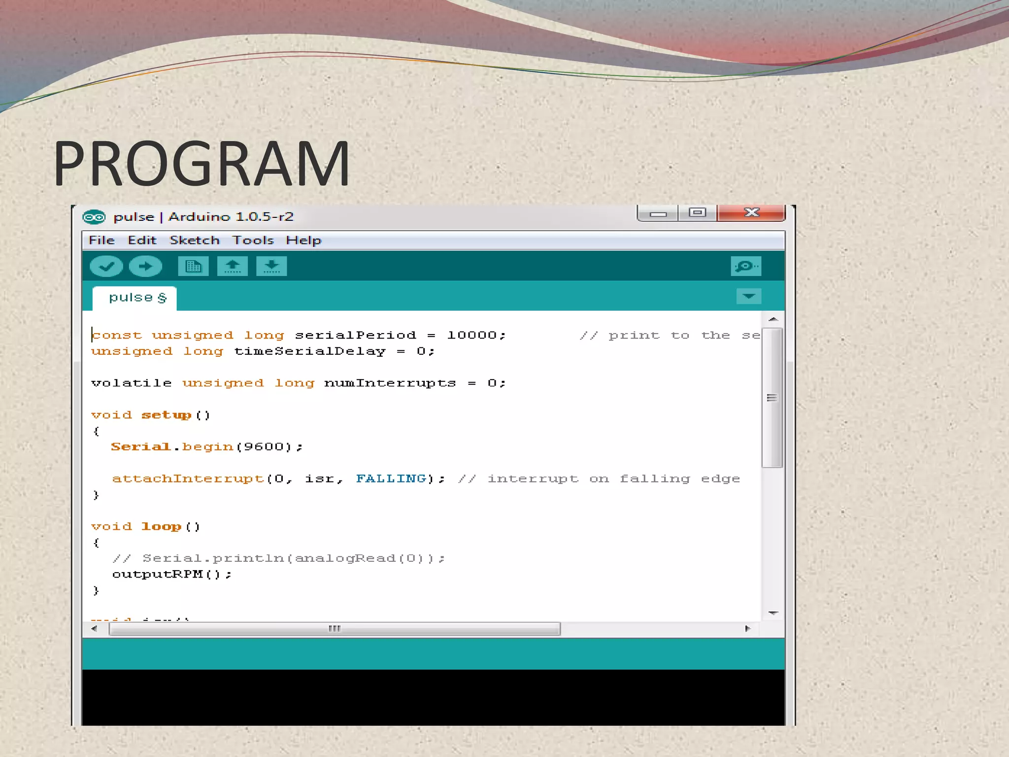
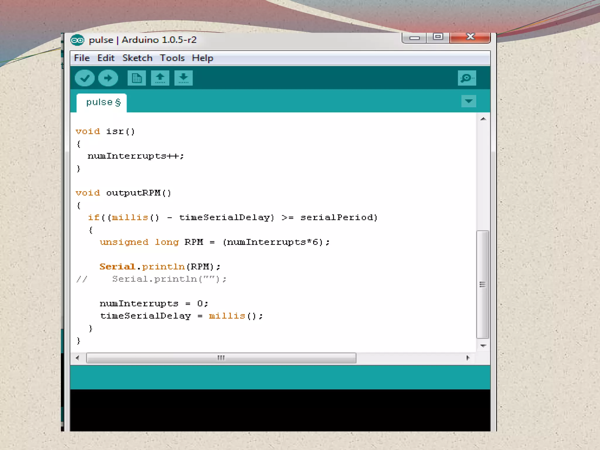
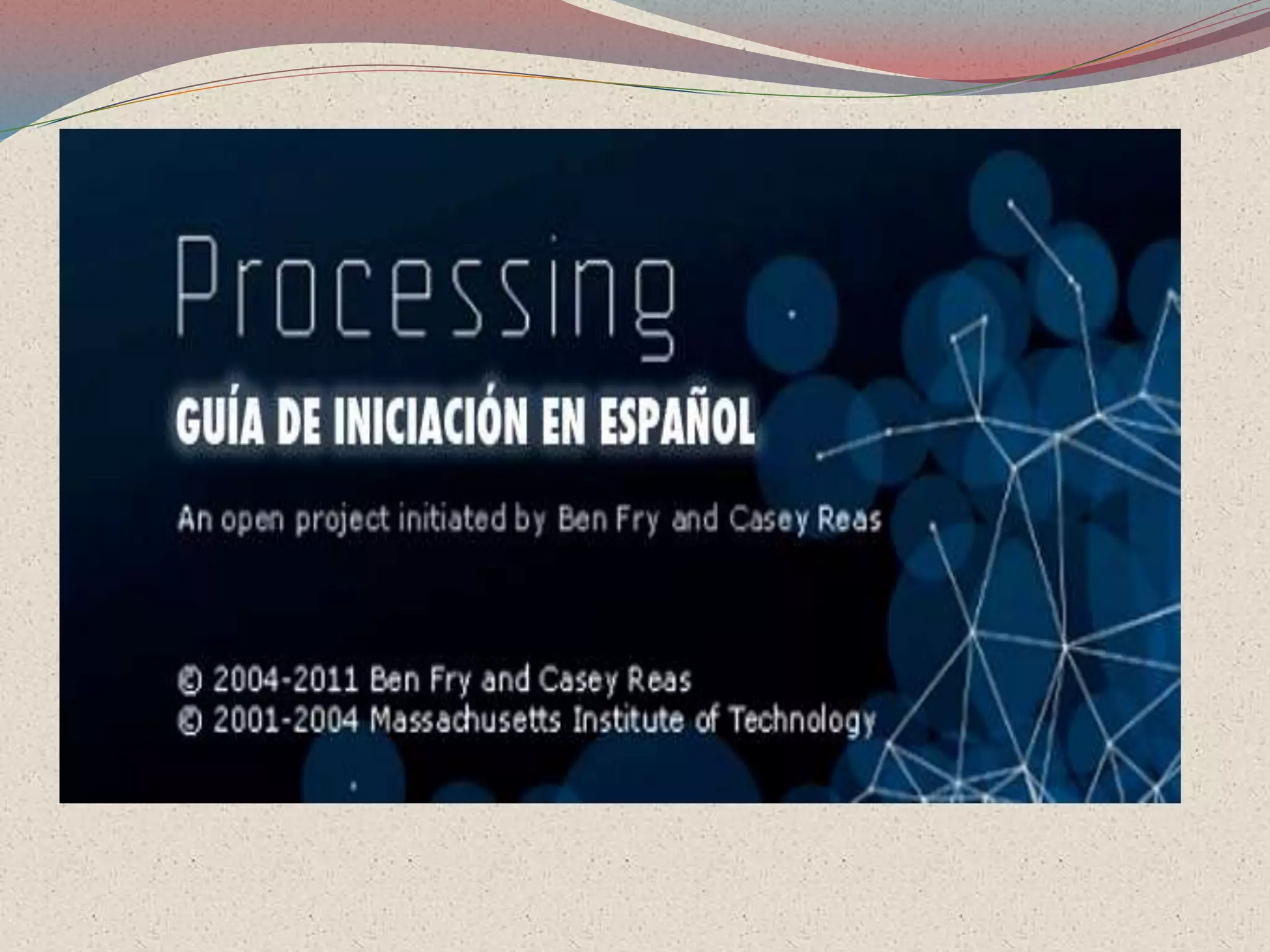
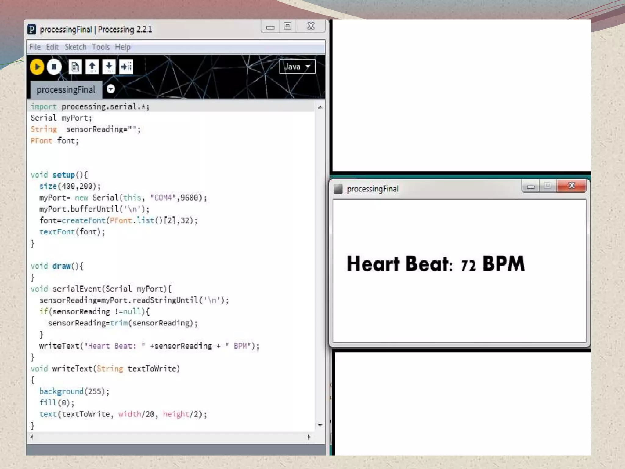
The project uses Arduino IDE and Processing for software development.
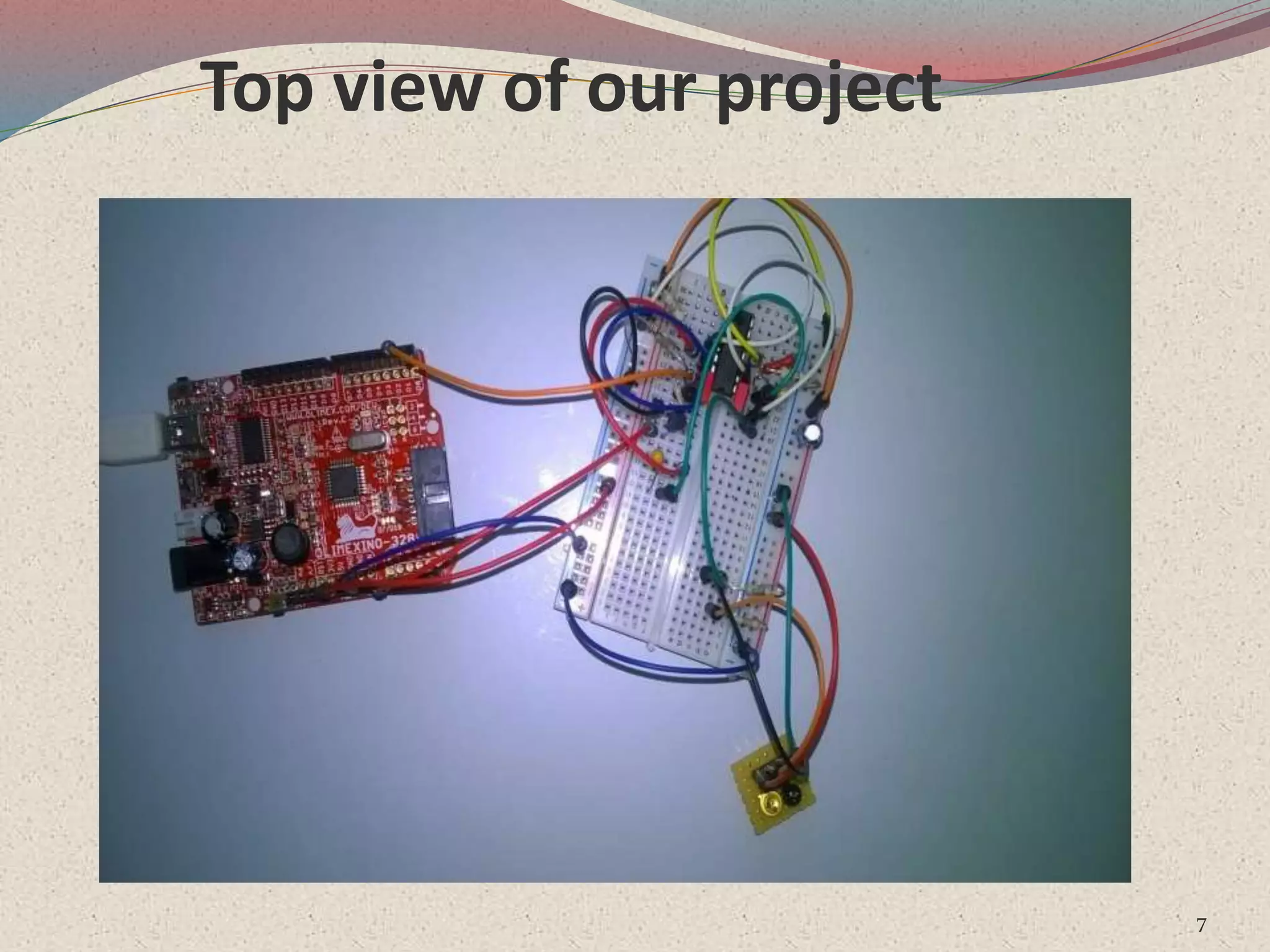
Top view illustration of the project setup.
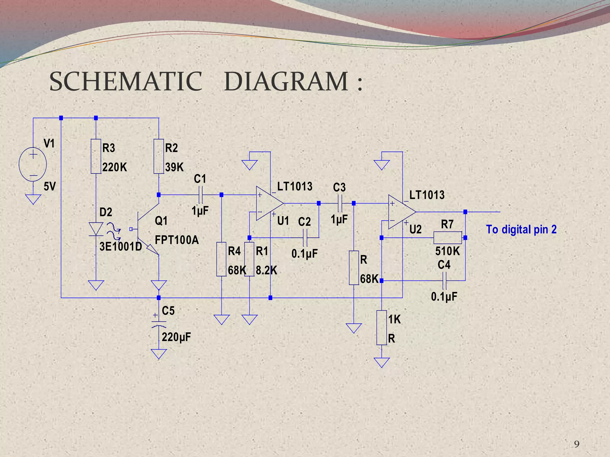
Utilizes components like IR LED, Phototransistor, LM324 Op Amp, and more for hardware implementation.
Detailed schematic diagram outlines various electrical components and their connections.
The IR sensor emits light and detects blood flow changes, translating it into an electrical signal.
The detected signals are processed through op-amps to establish a steady baseline and filter noise.
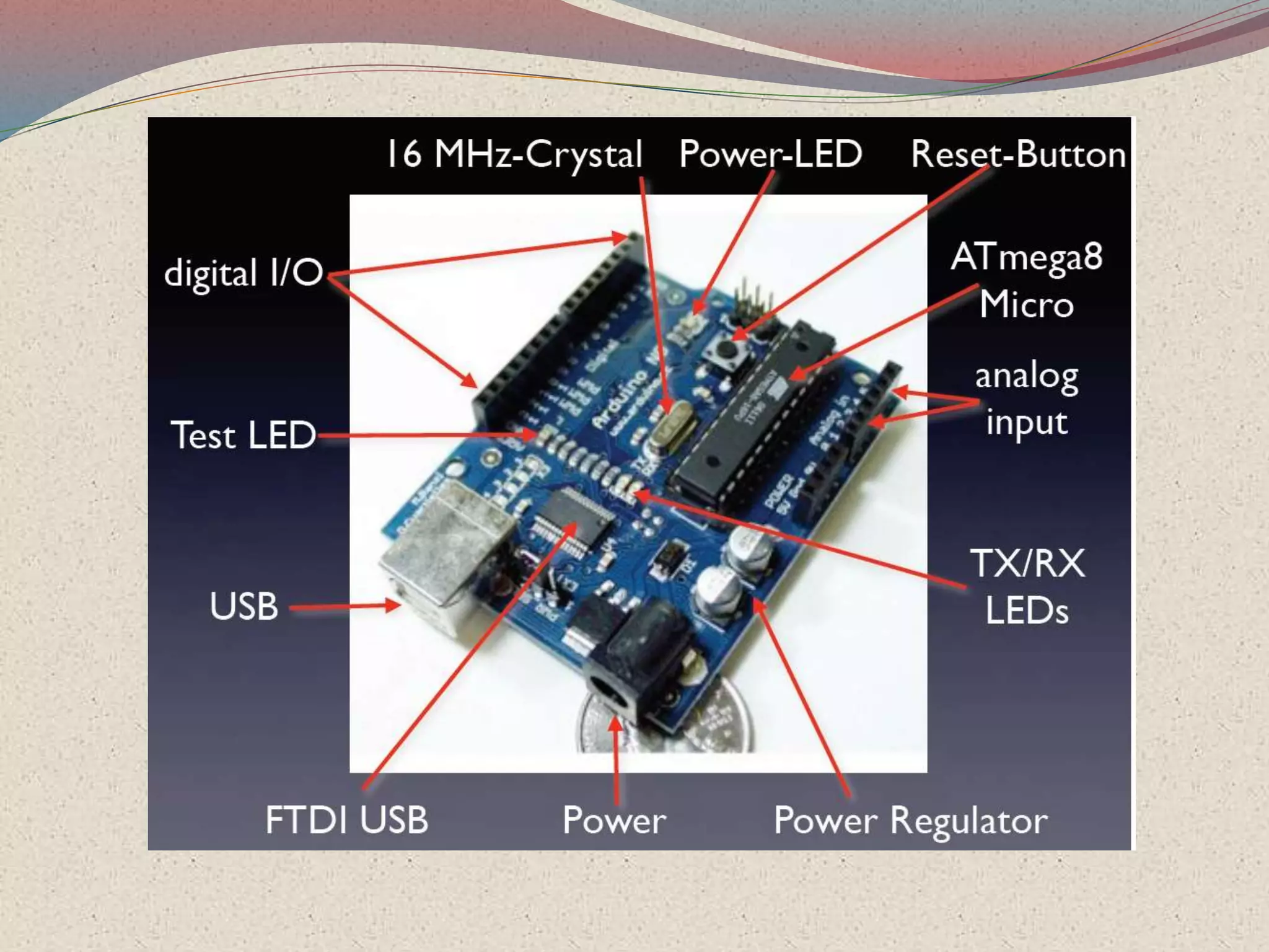
Arduino is a user-friendly microcontroller platform, ideal for various tech enthusiasts and projects.
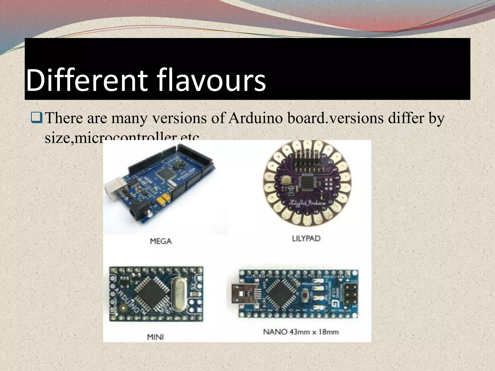
Different versions of Arduino boards vary in size and microcontroller capabilities.
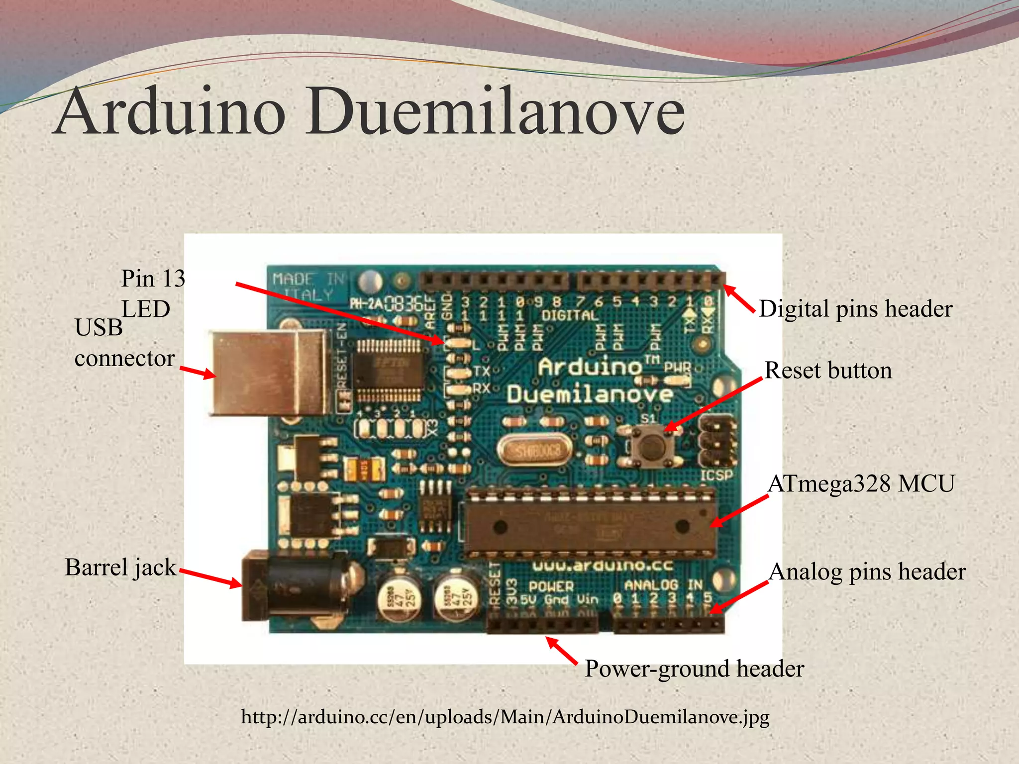
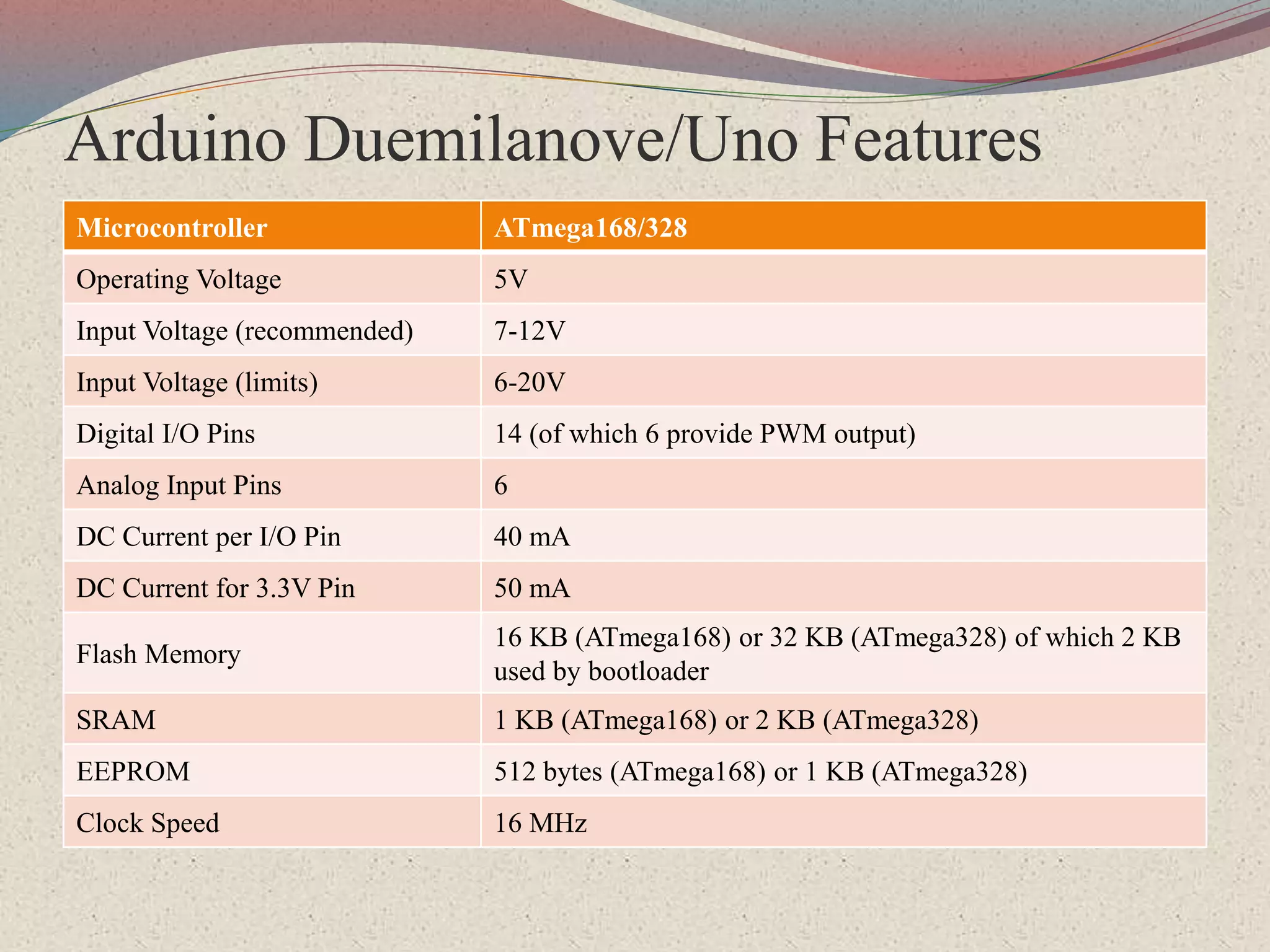
Detailed features and specifications of the Arduino Duemilanove include voltage and I/O pin details.
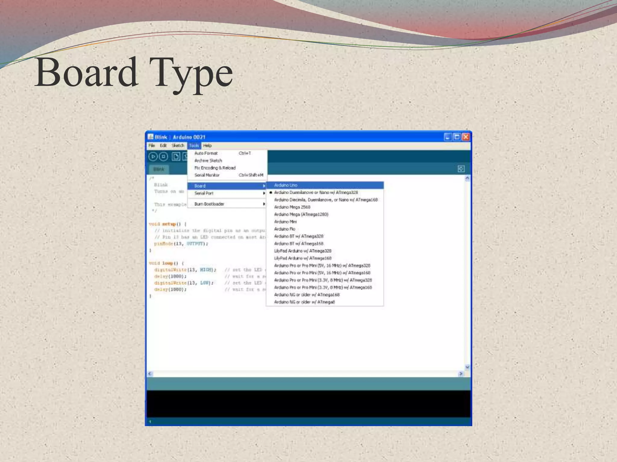
Different board types available under the Arduino umbrella.
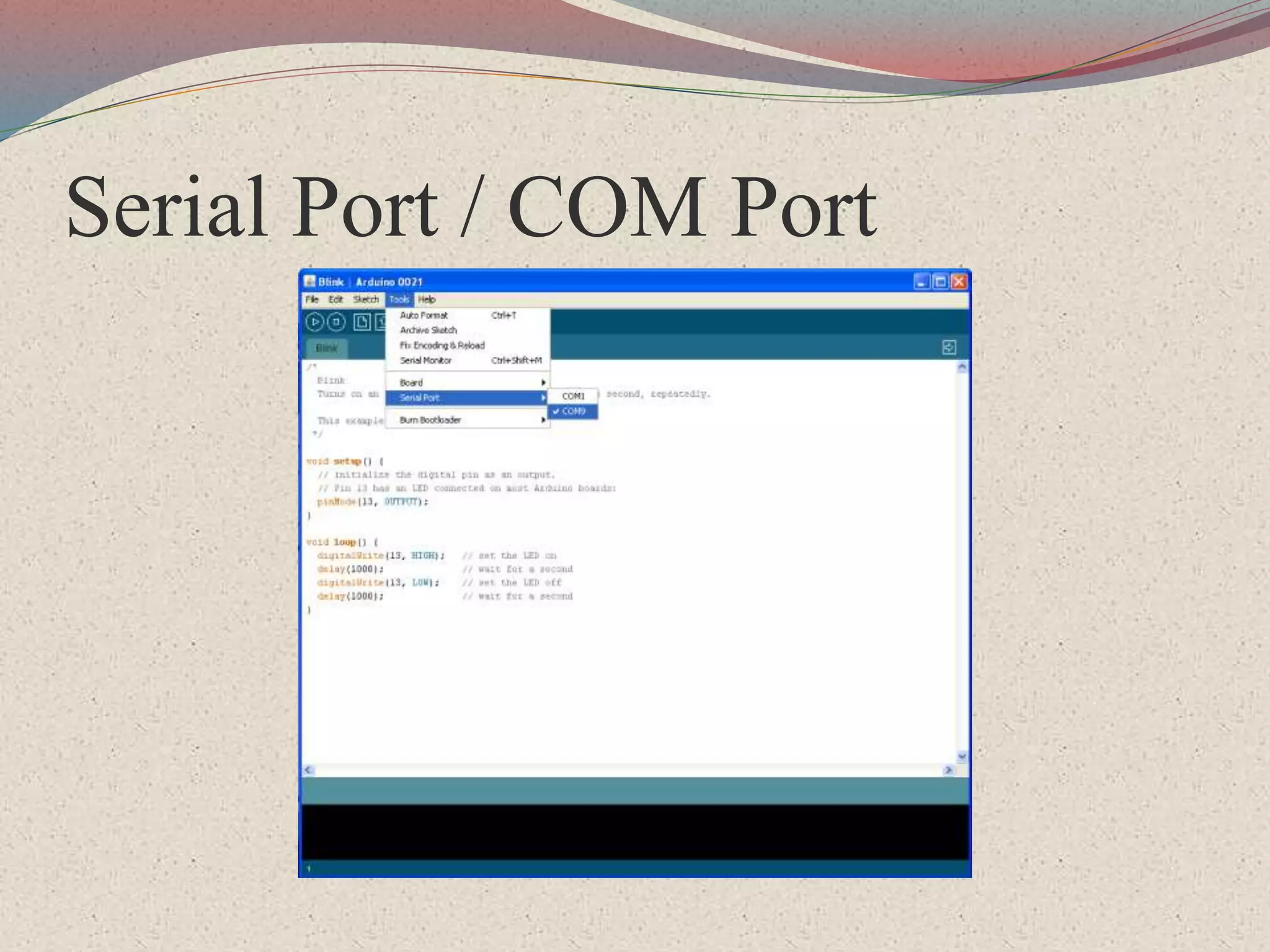
The use of Serial and COM ports for communication with Arduino devices.
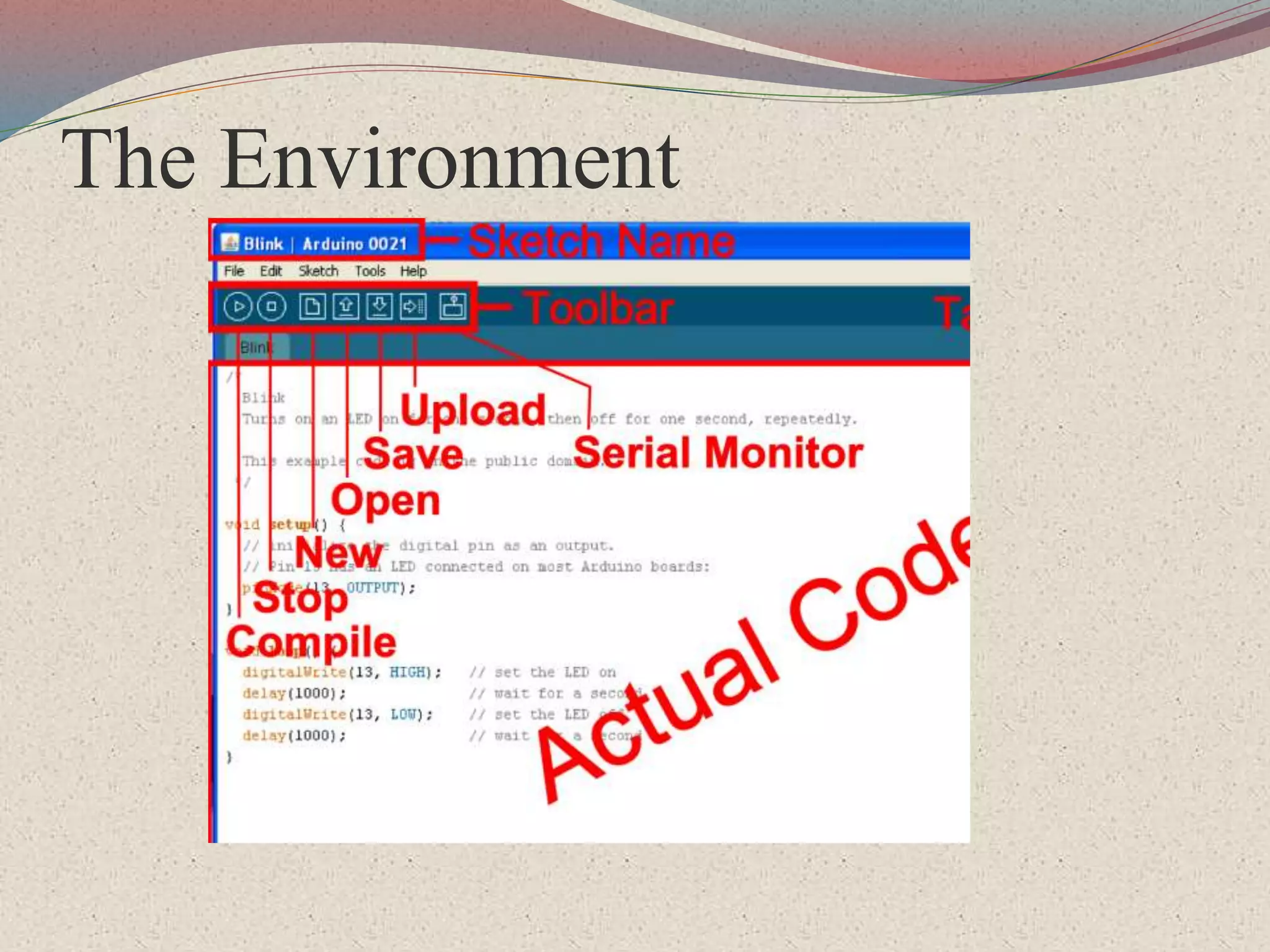
Overview of the environment used for programming with Arduino.
Processing is an open-source programming language for animations and interactions, developed at MIT.
A sketch in Processing serves as the basic file or project for creating visual outputs.
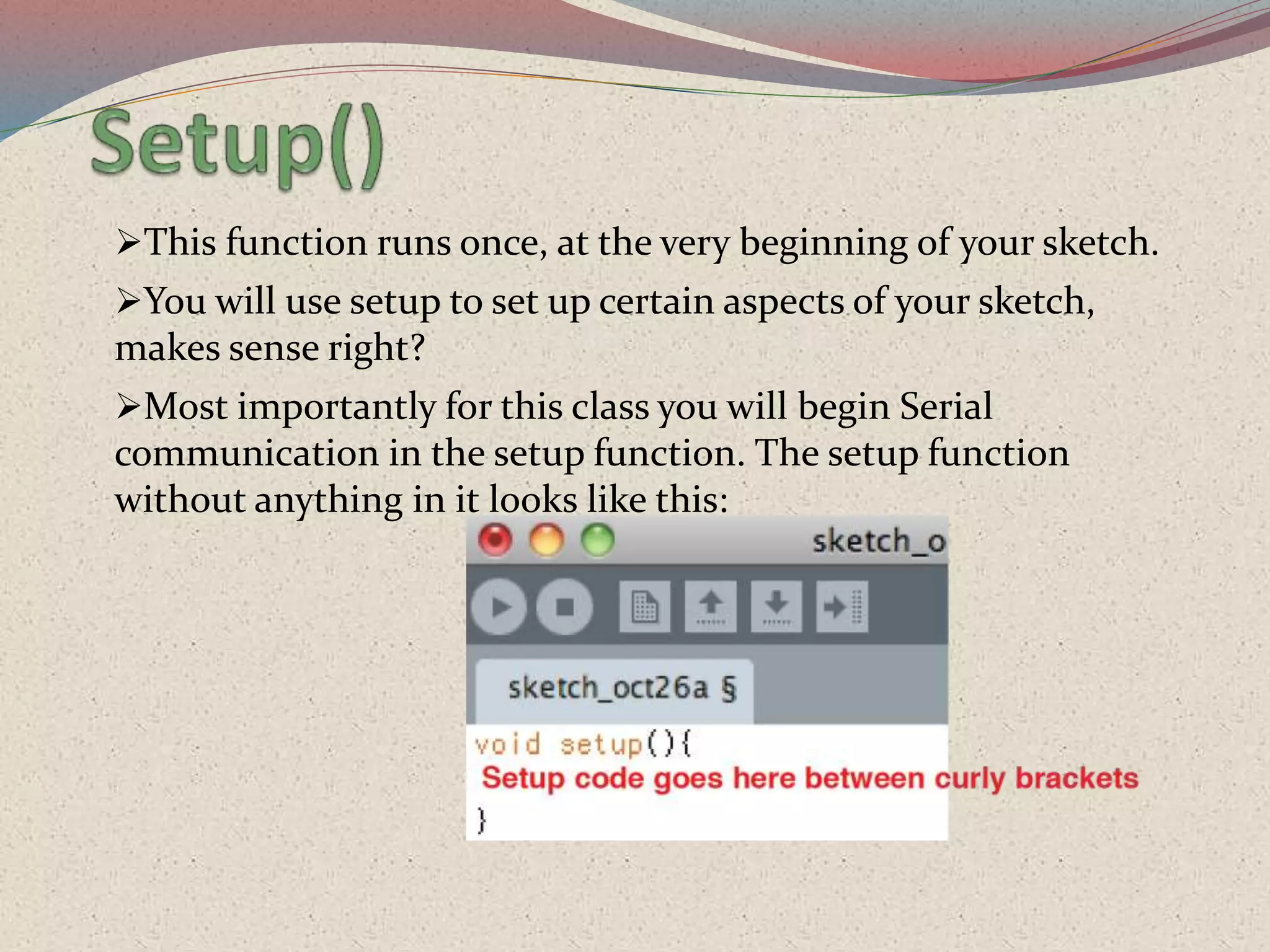
The setup function initializes settings in a Processing sketch and begins Serial communication.
The draw function executes repeatedly, performing shared operations in the Processing sketch.
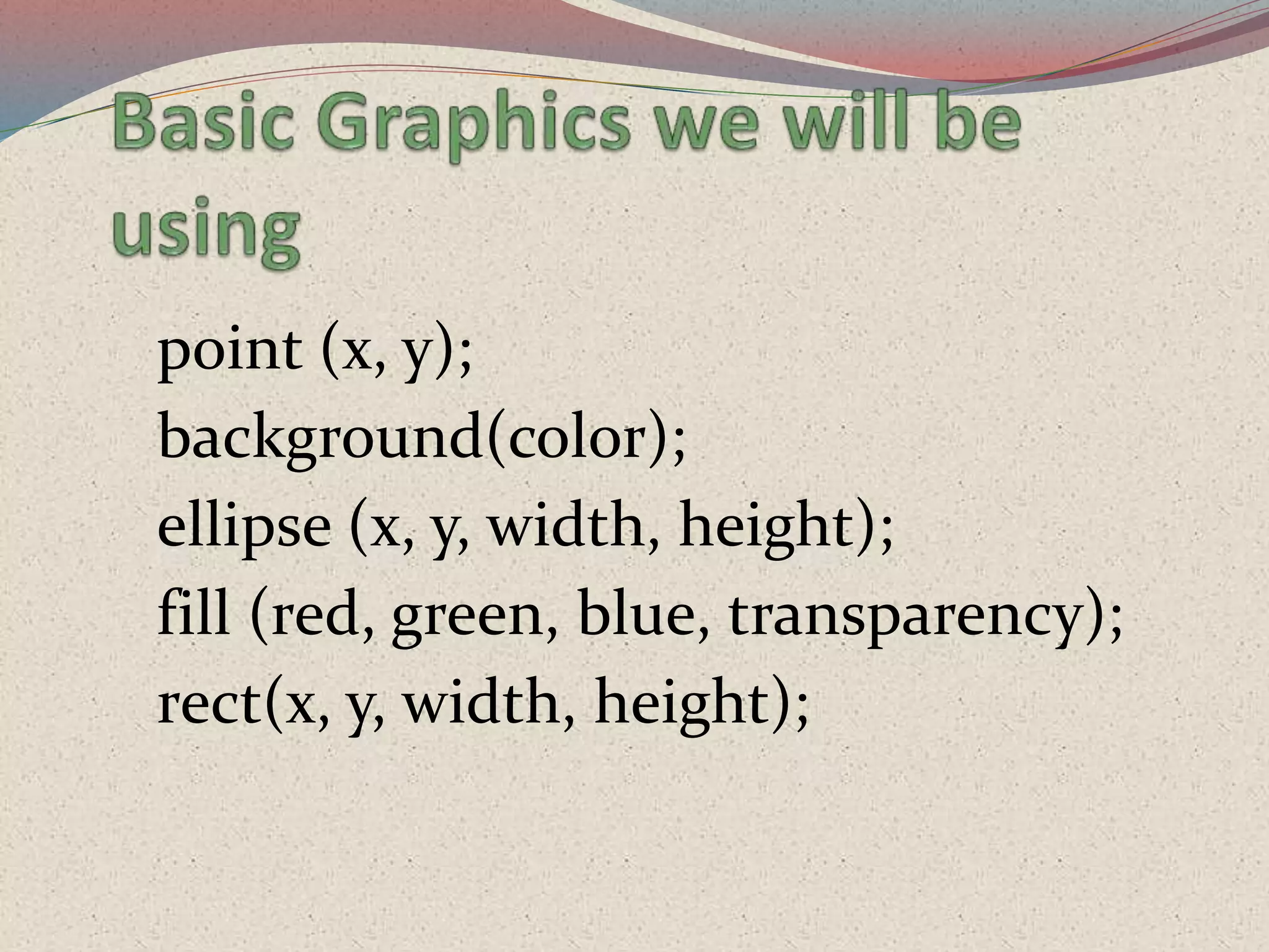
Common drawing functions such as background, ellipse, and rectangle used in sketches.
Convenient way to access the Processing Help Reference by highlighting code elements.
Current method inaccuracies; simpler logic can lead to varying results compared to advanced instruments.
Potential to monitor EEG and ECG, enabling continuous health monitoring and telemedicine for multiple patients.
Thank you note to the audience.